 Part of Tibidabo Scientific Industries
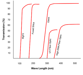
Photek intensifiers are available with a choice of input window materials. These include Glass, Fibre Optic, Fused Silica and MgF2. The diagram shows the UV cut-off and transmission for common input windows.
Photek are accustomed to processing a wide range of photocathodes. The transfer technique gives exceptional uniformity and low background noise. The graph below gives an outline of typical characteristics expected from photocathodes applied to our two most common substrates, fibre optic, and Fused silica. Photek does have the ability to tailor a photocathode to suit the desired frequency or sensitivity of the customer. For more details on this, and to discuss specific needs please contact us.
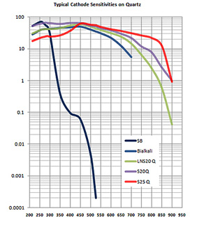
The above curves represent the broad spectral response that you would expect to achieve with Photek’s range of Gen II photocathodes. Please note that input window material and fast gating requirement will affect overall sensitivity.
Where fast gating below 10 ns is required Photek will provide a photocathode with mesh underlay.
Background Noise
The background noise is dominated by the choice of photocathode, and is not usually affected by the number of MCP’s or gain. Typical specifications are:
| Cathode Dark | Dark Noise |
| S20 | >200 cps/cm2 |
| Low Noise S20 | 30 – 50 cps/cm2 |
| Bialkali | 5 – 20 cps/cm2 |
| Solar Blind | < 5 cps/cm2 |
Image Intensifier Gain
Photek manufactures a range of image intensifiers with one, two or three MCPs (both single and double thickness), and with a variety of configurations. Typical gain against voltage characteristics for these tubes are shown.

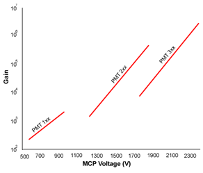
PMT Gain
Photek manufactures a range of PMT’s with one, two or three MCPs (both single and double thickness), and with a variety of configurations. Typical gain against voltage characteristics for these tubes are shown.
| Type (Colour) | Screen efficiency % (Optical Watts / Electrical Watt) | Peak Wavelength (nm) |
Photons / Electron @ 5 kV | Decay Characteristic | Decay Curves |
| P11 (Blue) | 5.9 | 446 | 120 | Fast initial decay with long decay at low level. 50 ms to 1% |
|
| P20 (Green) Fast | 12 | 540 | 320 | Fast initial decay with long decay at low level. 1 ms to 1% |
|
| P24 (Blue) | 5.0 | 500 | 120 | 10 ms to 10% | |
| P31 (Green) | – | 550 | – | 1 ms, good exponential | |
| P43 (Green) | 8.7 | 548 | 240 | 1.2 ms/decade, true exponential | |
| P46 (Green) | 1.8 | 530 | 55 | 300 ns | |
| P47 (Blue) | 3 | 410 | 64 | 80 ns | |
| FS | 4.2 | 513 668 768 |
96 | 12 us to 10 % | |
| GOS | 0.7 | 420 | – | 50 ns to 10 % 110 ns to 1 % |
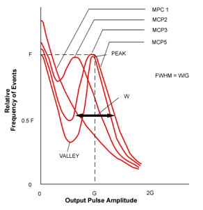
Single MCP intensifiers have an exponential pulse height distribution. For photon counting image intensifiers, pulse height distribution is measured during processing to optimise channel plate out gassing. The diagram below shows how the number of MCPs affect the pulse height distribution. Both the peak/valley ratio, and the FWHM of the pulse height distribution are used as indications of the quality of photon counting tubes. It can be seen that both of these parameters improve, as the number of MCPs is increased.
Photek use the American MIL Spec technique based on the USAF test pattern (1951) to measure limiting image intensifier resolution. The limiting resolution steps on this pattern are large, 20, 23, 25, 28, 32, 36, 40 lp/mm and the limiting resolution is quoted as the mean value achieved in two orthogonal directions. Because the pattern consists of only three short bar pattern in each direction, the result is not particularly favourable to Photek compared to the other techniques described above.
Limiting resolution is dominated by MCP pore/pitch as shown below:
| Tube Size | MCP Pore Size | Typical Limiting Resolution with P43 Phosphor * |
| 18 mm, 25 mm | 6/8 | 40 lp/mm |
| 40 mm | 10/12 | 26-36 lp/mm |
| 75 mm, 150 mm | 25/32 | 10-15 lp/mm |
These values are quite consistent with the MCP. For example, with 12 micron pitch, there are 80 MCP pores per mm, corresponding to 40 lp/mm if the test pattern is perfectly aligned with the MCP. Since it has a hexagonal structure, it is impossible to align it in two directions at 90° to each other.
High gain tubes are most commonly used in photon counting systems. The superior pulse height distribution is used to discriminate between photon events and electronic noise and the resolution performance can be recovered by suitable event-processing software. Photon counting systems can in fact achieve resolution only limited by the size of the microchannel plate pores (usually 10 microns).
* Phosphor particle size does effect resolution and should be considered.
Uniformity can be based on scans across the complete tube in x-y axis, or in a defined zone using standard Deviation/Mean measurement:
| Tube Size | X-Y Scan | Standard Deviation |
| 18 mm | (Typical ±10%) | 7% |
| 25 mm | (Typical ±12%) | 10% |
| 40 mm | (Typical ±15%) | 12% |
| 75 mm | (Typical ±17%) | 15% |
Most of Photek image intensifiers are sold for applications with CCD or CMOS sensors and employ a square or rectangular zone. Typical specification for these zones are:
| Tube Type | Black Spots 75-100 Microns | Black Spots 101-150 Microns | Uniformity % Standard Deviation/Mean |
| MCP125 | <3 | <2 | 7% |
| MCP225 | 3 | 2 | 10% |
| MCP140 | 4 | 2 | 10% |
| MCP240 | 6 | 2 | 12% |
| MCP175 | 10 | 5 | 15% |
| Cathode | MCP Input | MCP Intermediate | MCP Output | Screen | |
| Single MCP | -200V | 0V | – | 900V | 6350V |
| Double MCP | -200V | 0V | 850V | 1800V | 7300V |
| Triple MCP | -200V | 0V | 850V | 2700V | 8200V |
Typical operating voltages (Actual operating voltages are provided with each intensifier)
Mechanical
Tubes are normally potted in a plastic housing using a silicone rubber. Other encapsulates are available on request. Photek will encapsulate the tube to customers specifications, and can apply transparent earthed coatings to optics as required.
| Size | Standard | With PSU | ||
| Length | Diameter | Length | Diameter | |
| 25mm | 25 | 52.7 | 29 | 99 |
| 40mm | 25 | 71 | 29 | 99 |
| 75mm | 29 | – | 29 | – |
| 150mm | 26 | 177 | 41 | 270 |
(Typical dimensions for standard housed tubes).
Environmental
Operational Limits: -40°C to +45°C
Short Term Storage: -40°C to +65°C
The vacuum interface devices are mounted on UHV vacuum flanges, based on the established Conflat®; design, in which a precision OFHC copper gasket is captured between two knife edge sealing surfaces. They are also available mounted on ISO and other ‘O’ ring sealed flanges with an equivalent tubulation to the conflat mounted detectors.
| Flange Size | Detectors | ||||||||
| Nominal OD/ID |
VID-12 | VID-18 | VID-25 | VID-40 | VID-75 | VPM-6 | VPM-12 | VPM-25 | VPM-40 |
| CF35 70mm/35mm |
S | S | N | N | N | S | N | N | N |
| CF63 114mm/63mm |
O | S | S | N | N | O | S | N | N |
| CF100 152mm/100mm |
O | O | O | S | N | O | O | S | N |
| CF150 203mm/150mm |
O | O | O | O | S | O | O | O | S |
| CF200 254mm/200mm |
O | O | O | O | O | O | O | O | O |
| CF250 304mm/250mm |
O | O | O | O | O | O | O | O | O |
| S – Standard Configuration | O – Optional Configuration | N- Not Available | |||||||||
